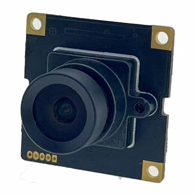


Product Description
The DV-330EH puts a 960 × 720 CMOS sensor on a conventional CVBS output, so it drops onto existing coax and recorders. NTSC models output 720 × 480i, PAL models 720 × 576i; 700 TVL is available when the recorder samples 960H. A 2.2 mm M12 lens covers 79° × 61°. It runs from 24 V AC or 12 V DC on two conductors - at 1.8 W, 75 mA or 150 mA, which is why 24 V AC reaches four times the cable distance. The die-cast body measures 45.4 × 41 × 28.6 mm, weighs 94.2 g, and carries a 300 mm pigtail splitting to BNC video and two-pin power.

Product specification
2.1 Model numbering
|
Model |
Video standard |
Taken from the part number |
|
DV-330EH-N208 |
NTSC, 60 Hz field rate |
N = NTSC. 330EH = body and board revision. |
|
DV-330EH-P208 |
PAL, 50 Hz field rate |
P = PAL. 208 is a platform code - it is not the lens focal length, which is 2.2 mm. |
Both models share one board, one lens and one housing. The only difference is the encoder and its crystal.
2.2 Sensor and video
|
Parameter |
Value |
Note |
|
Image sensor |
1/2.8″ CMOS, 960 × 720 |
0.69 MP. Part number and pixel pitch to be confirmed. |
|
Scanning |
2:1 interlaced |
Required by the CVBS standard; the sensor itself is progressive. |
|
Horizontal resolution |
700 TVL |
Only realised on a 960H front end - see 3.2. |
|
Video output |
CVBS, 1.0 V p-p into 75 Ω, sync negative |
Levels verified against 100 / 40 / 40 IRE in table 12. |
|
Sync system |
Internal only |
No line-lock; on AC24V this allows roll when switching between cameras. |
|
S/N ratio |
30 dB |
The measurement condition is not stated. |
|
Dynamic range |
72 dB |
A single exposure figure, not wide dynamic range. |
|
Minimum illumination |
0.1 lux |
F-number, shutter, AGC gain and IRE target are all unstated. |
|
Day / night |
Software switch, default OFF |
No IR-cut filter removal, so the camera stays in colour at night. |
|
Digital zoom |
1.3× |
738 × 554 effective; horizontal resolution falls to about 540 TVL. |
2.3 Lens and field of view
|
Parameter |
Value |
|
Lens mount |
M12 × 0.5, fixed focus |
|
Focal length |
2.2 mm |
|
Field of view (stated) |
79° H × 61° V |
|
F-number / iris |
To be confirmed |
|
IR-cut filter |
Fixed, not removable |
2.4 Image processing - menu states, not specifications
|
Menu item |
Factory default |
Available |
What it changes |
|
Day / night |
OFF |
ON / OFF |
Colour to black-and-white matrix. Without IR-cut removal the sensor still sees IR, so the switch does not add sensitivity. |
|
Auto electronic shutter |
AUTO |
AUTO, 1/60 to 1/100 000 s |
Exposure. This is the setting that has to be pinned down for any low-light claim. |
|
Noise reduction |
3D DNR on |
OFF / LOW / MID / HIGH |
Trades smear on moving objects for noise. |
|
White balance |
AUTO |
AUTO / INDOOR / OUTDOOR / MANUAL |
Correction range 1800–10500 K indoors, 6500–10500 K outdoors. |
|
Image flip |
OFF |
OFF / H / V / H+V |
Ceiling and mirror mounting without a second bracket. |
|
Wide dynamic range area |
OFF |
ON / OFF, region selectable |
Applies a tone curve to one area only; the 72 dB sensor figure is unchanged. |
|
Privacy zones |
OFF |
Up to 4 zones |
Masks an area in the video itself, not in the recorder. |
|
Digital zoom |
1.3× |
1.0–1.3× |
Crops the 960 × 720 raster; resolution drops with the crop. |
How these are reached is not stated anywhere on the page. There is no joystick, no UTC-over-coax support and no OSD control pin in the connector. On a camera where six of the eight rows above read "OFF", that is the first question an installer asks.
2.5 Electrical
|
Parameter |
Value |
Note |
|
Input voltage |
AC24V ±10 % (21.6–26.4 V), 50/60 Hz, or DC12V ±10 % (10.8–13.2 V) |
Both land on the same two conductors, CN1 pins 3 and 4 - see 4.1. |
|
Power consumption |
1.8 W max |
150 mA at 12 V DC, 75 mA at 24 V AC. |
|
Reverse polarity |
Not specified |
Required if DC12V shares pins with AC24V. |
|
Surge / ESD |
Not specified |
24 V AC field wiring is normally subjected to 1 kV comb waves. |
|
Over-current protection |
Resettable PTC in the harness |
On the power pair only; the video pair is unprotected. |
2.6 Mechanical
|
Parameter |
Value |
Note |
|
Body |
41 × 30 × 28.6 mm |
Height × width × depth, excluding lens. |
|
Front flange |
45.4 × 41 mm |
Larger than the body; allow for it in a recessed mount. |
|
Overall height with lens |
41.7 mm |
Lens protrudes 13.1 mm from the front face. |
|
Mounting |
4 × M2 on 30 × 30 mm, plus 4 × M2 at the rear |
8 tapped holes in total, as marked on the drawing. |
|
Lens thread |
Ø14 mm, flange Ø15 mm |
Standard M12 lens seat. |
|
Weight |
94.2 g |
Consistent with a die-cast zinc-magnesium shell of this size. |
|
Connector position |
Right side, 4.5 mm from the front face, 1.25 mm pitch, 4 circuits |
Mating plug 12.1 mm deep; leave 20 mm behind the camera. |
|
Dimensions (source table) |
199.9 × 92.7 mm |
Matches none of the three drawings. Replace with the four rows above. |
2.7 Environment and compliance
|
Parameter |
Value |
Note |
|
Operating temperature |
−30 °C to +70 °C |
Stated; no humidity figure for operation. |
|
Storage |
−40 °C to +80 °C, 0–90 % RH |
Humidity is given for storage only. |
|
Ingress protection |
Not specified |
The housing closes with four screws and the cable enters through an unsealed side wafer. An IP rating is mandatory before this is sold for outdoor use. |
|
Impact resistance |
Not specified |
"High-strength collision protection" is not an IK rating. |
|
Housing material |
Die-cast zinc-magnesium alloy |
Chosen for stiffness and EMI shielding at low mass; not a corrosion specification. |
|
Certification |
CE, FCC, RoHS - on request |
None of the three appears on the current page. |
Interface & pin definition
4.1 CN1 - 4-pin 1.25 mm wafer
|
Pin |
Signal |
Direction |
Harness wire |
Note |
|
1 |
CVBS |
Out |
Yellow |
1.0 V p-p into 75 Ω. Labelled VIN on the cable drawing, which reads as a power input. |
|
2 |
GND |
- |
Black |
Shared return for video and power. No separate signal ground and no shield pin. |
|
3 |
AC-L |
In |
Black |
24 V AC line. Also the negative landing point if DC12V is used. |
|
4 |
AC-H (housing drawing) / AC-N (cable drawing) |
In |
Red |
24 V AC neutral, or DC positive. The two drawings disagree, and the red wire is on the neutral. |
4.2 Video level, checked in IRE
The three level figures in the source table are correct, and they are the strongest evidence on the page that the analogue side was engineered rather than copied. 714 mV is exactly 100 IRE; 286 mV is 40 IRE, the standard sync and burst amplitude.
|
Parameter |
Specification |
IRE |
Comment |
|
Video level, white |
714 ± 70 mV |
100 |
0.714 V above blanking level. |
|
Sync level |
286 ± 35 mV |
40 |
Sync tip to blanking. |
|
Burst level |
286 ± 35 mV |
40 |
9 ± 1 cycles of 3.579545 MHz on the back porch. |
|
Nominal output |
1.0 V p-p into 75 Ω |
140 |
White to sync tip. |
Keep this table and label the column IRE. It turns three bare millivolt values into a specification an integrator can verify with a scope in ten seconds.
4.3 Cable assembly
|
Item |
Specification |
Note |
|
Camera end |
4-pin 1.25 mm wafer, overmoulded |
30 ± 3 mm moulded section behind the plug. |
|
Video leg |
BNC female, Ø12.5 mm flange, 75 Ω |
64-carrier braided coax. "64 series" on the drawing refers to the braid count, not to a cable standard. |
|
Power leg |
Molex 5557, 2 circuits, 4.2 mm pitch |
Red positive, black negative, Ø3.0 mm jacket. |
|
Length |
300 ± 20 mm from the split to the wafer |
The 80 ± 10 mm dimension runs to the PTC. |
|
Protection |
Resettable PTC on the power pair |
Hold current not stated; the video pair has no protection. |
4.4 Why dual power matters: voltage drop over the run
At 1.8 W the camera draws 150 mA from 12 V but only 75 mA from 24 V. A cable loses voltage in proportion to current, so the same pair of wires carries a 24 V AC camera roughly four times as far as a 12 V DC one before it falls outside ±10 %.
|
Conductor |
12 V DC at 150 mA |
24 V AC at 75 mA |
Ratio |
|
0.20 mm² (24 AWG) |
46 m |
183 m |
4.0× |
|
0.50 mm² (20 AWG) |
114 m |
457 m |
4.0× |
|
0.75 mm² (18 AWG) |
171 m |
686 m |
4.0× |
|
1.00 mm² (17 AWG) |
229 m |
914 m |
4.0× |
Loop resistance at 20 °C, copper at 0.0175 Ω·mm²/m: L = ΔV / (2 × I × ρ / A). The video run is a separate question and is limited by high-frequency loss in the coax, not by this table.
Sell it this way. A 250 m perimeter run on 0.5 mm² works on 24 V AC and does not work on 12 V DC. That single sentence is worth more than the word "flexible", and it is the only argument that survives a site survey.
Dimensions


Typical applications
|
Application |
Why this camera fits |
Confirm before quoting |
|
Perimeter and car park, existing coax and DVR |
No re-cabling, no switch, no NVR. Plugs into the recorder already in the cabinet. |
Recorder must sample 960H for 700 TVL; 12 V DC runs stop at 114 m on 0.5 mm². |
|
Lift cars, stairwells, plant rooms |
41 × 30 × 28.6 mm body and a 30 × 30 mm M2 pattern fit where an IP dome will not. |
Needs at least 3 lux of ambient light - there is no IR illumination and no IR-cut removal. |
|
Industrial cells with dust or washdown |
Die-cast zinc-magnesium body, −30 to +70 °C, no fan, no network stack to crash. |
No IP rating, so an external enclosure is required. Ask about the washdown chemicals before recommending the alloy. |
|
Replacing an ageing CCD camera in a legacy estate |
Same BNC, same two power wires, same recorder channel. |
No line-lock: on AC24V, vertical phase drifts between cameras when the DVR switches channels. |
Not the right fit for night-only outdoor monitoring, for anything that needs more than 700 TVL, for face or plate recognition, or for a site that is being cabled for IP anyway. Saying so on the page saves a sample round and a return.
Customization & ordering
|
Option |
Available |
Effect on the order |
|
Video standard |
NTSC (N208) / PAL (P208) |
Encoder and crystal only. Lead time is unaffected. |
|
Focal length |
2.2 mm / 3.6 mm / 6 mm, M12 |
Changes the field of view: 3.6 mm gives about 71° × 57° on a 1/2.8″ sensor. Re-qualify the lens before quoting. |
|
Power |
Dual AC24V / DC12V, or single-source |
Recommend a separate SKU for a DC-only build so the pin definitions in 4.1 can be unambiguous. |
|
Cable |
300 mm standard; 1 m, 3 m and 5 m on request |
Longer tails change the voltage-drop arithmetic in 4.4 only marginally; the BNC and 5557 ends stay the same. |
|
Branding |
Laser mark on the front flange |
45.4 × 41 mm of flat area, 30 × 30 mm clear of the screws. |
|
Certification |
CE, FCC, RoHS on request |
State the test house and the report number on the quotation. |
Hot Tags: cvbs camera with dual power, China cvbs camera with dual power manufacturers, suppliers, factory, ccd camera for spectroscopy, astronomy ccd camera, best ccd digital camera, industrial ccd camera, color cmos ccd camera, ccd dome camera